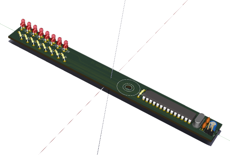
ATmega8-POV: Building a Simple Persistence-of-Vision Display
Persistence-of-vision (POV) displays create the illusion of a continuous image by rapidly flashing LEDs in a sequence as they move across a fixed path. This project, ATmega8-POV, showcases how to build a simple POV display using the ATmega8 microcontroller. Designed with the free PCB design software KiCAD, this project offers a fantastic way to dive into microcontroller programming and PCB design.
What is ATmega8-POV?
ATmega8-POV is a project that leverages the concept of persistence of vision, where fast-moving LEDs create an illusion of continuous text or patterns visible to the human eye. The project uses an ATmega8 microcontroller to control a set of LEDs, switching them on and off in a rapid sequence to display patterns or text as the device moves. The PCB for this project was designed in KiCAD, providing an easy-to-replicate circuit layout for hobbyists and engineers.
Project Overview
The project involves several key components and steps, including:
- ATmega8 Microcontroller: The "brain" of the POV display, which handles the timing and sequence for lighting up the LEDs.
- LED Array: A series of LEDs controlled by the microcontroller. The LEDs light up in specific patterns that, when moved rapidly, create readable text or images.
- Power Supply: Typically, a battery powers the ATmega8 and LEDs.
- PCB Design in KiCAD: This design step involves creating a PCB layout that aligns with the LED positioning and microcontroller connections.
Hardware and Components Required
To build the ATmega8-POV, you’ll need:
- ATmega8 Microcontroller: This microcontroller will handle the LED sequences.
- LEDs (8-12): These will be used to display the POV effect.
- Resistors (typically 220Ω or 330Ω) for current limiting on each LED.
- Capacitors for stabilizing power input to the microcontroller.
- Power Supply: A small battery pack, such as 3V or 5V, to power the board.
- PCB designed in KiCAD or a breadboard for prototyping.
Designing the Circuit in KiCAD
The design process in KiCAD involves several steps:
- Schematic Design: Draw a schematic with the ATmega8 microcontroller connected to the LED array. Each LED should have a resistor to limit current, and you may add bypass capacitors near the power pins of the microcontroller for stability.
- PCB Layout: Convert the schematic to a PCB layout. Place the ATmega8 and LEDs on the board in a way that minimizes trace lengths and makes it easy to mount the device for motion.
- Export and Manufacture: Once the PCB layout is complete, generate the necessary Gerber files, which can be sent to a manufacturer for PCB production.
Programming the ATmega8
The ATmega8 needs to be programmed to light up the LEDs in specific sequences to form patterns or letters. Here's a high-level guide to the code structure:
- Initialize the ATmega8: Set the data direction register for the LED pins as output.
- LED Sequence Logic: Create a loop where each LED lights up in a specific order. This sequence could represent letters, numbers, or simple patterns.
- Timing and Delay: Add delays to control the duration each LED is on, ensuring that patterns are visible when the display is moved at a certain speed.
Mounting and Testing
Once you’ve assembled the components and programmed the ATmega8, the next step is to test the display:
- Mount the PCB on a structure that allows it to move (e.g., attach to a fan blade or motor arm).
- Power On: Ensure the power supply is sufficient to keep the LEDs bright.
- Test and Adjust: Test the timing of the display by moving the PCB. Adjust delays in the code as necessary to improve readability.
Enhancements and Customization
Here are a few ideas to take this project further:
- Variable Text Display: Update the code to allow for different text or patterns to display on each cycle.
- Wireless Control: Integrate a wireless module (like Bluetooth) to change text or patterns in real time.
- Battery Optimization: Add power-saving techniques to extend battery life during operation.
Conclusion
The ATmega8-POV is a fantastic introduction to microcontroller programming and PCB design, allowing creators to explore concepts in timing, LED control, and basic electronics. By designing and building this project, you’ll gain hands-on experience with persistence of vision, an engaging and rewarding display technique. Plus, KiCAD’s user-friendly interface makes it accessible for creating and customizing your PCB layouts.
Give this project a try and enjoy the mesmerizing light show as your ATmega8-powered display brings text and patterns to life!
You can find the PCB Design using KiCAD and additional resources on the project’s GitHub page:
