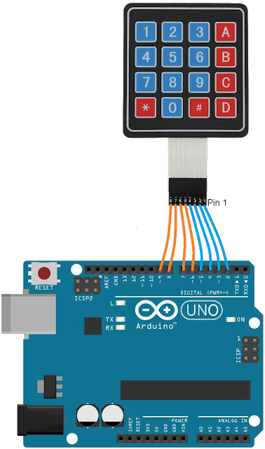
#include <Keypad.h>

const byte ROWS = 4; //four rows
const byte COLS = 4; //four columns
char keys[ROWS][COLS] = {
  {'1','2','3','A'},
  {'4','5','6','B'},
  {'7','8','9','C'},
  {'*','0','#','D'}
};

byte rowPins[ROWS] = {9,8,7,6}; //Rows 0 to 3
byte colPins[COLS]= {5,4,3,2}; //Columns 0 to 3

Keypad keypad = Keypad( makeKeymap(keys), rowPins, colPins, ROWS, COLS );
int bufferLength = 5;
int bufferIndex = 0;
char bufferData[5];

void setup(){
   Serial.begin(9600);
}

void loop(){
  char key = keypad.getKey();
  if (key != NO_KEY){
    //Serial.write(key);
    bufferData[bufferIndex] = key;
    bufferIndex++;
  }
  if(bufferIndex>=bufferLength){
    for(int i=0; i < bufferLength; i++) {
      Serial.print( bufferData[i] );
    }
    //reset all the functions to be able to fill the string back with content
    bufferIndex  = 0;
    Serial.println();
  }
}
Let's break down the code step by step.
Code Explanation
1. Importing the Keypad Library
#include <Keypad.h>
The Keypad library simplifies working with a matrix keypad by handling key detection and mapping the correct characters to each key press.
2. Defining Rows and Columns
const byte ROWS = 4; //four rows
const byte COLS = 4; //four columns
Here, ROWS and COLS are constants that define the number of rows and columns in the keypad (4x4).
3. Key Mapping
char keys[ROWS][COLS] = {
  {'1','2','3','A'},
  {'4','5','6','B'},
  {'7','8','9','C'},
  {'*','0','#','D'}
};
The keys array defines the characters associated with each key on the keypad. Each key is mapped to a character in a 4x4 grid, so pressing a certain button will return its corresponding character (like '1', '2', '3', 'A', etc.).
4. Specifying the Pin Connections
byte rowPins[ROWS] = {9,8,7,6}; // Rows 0 to 3
byte colPins[COLS]= {5,4,3,2}; // Columns 0 to 3
The rowPins and colPins arrays define which Arduino pins are connected to the keypad’s rows and columns. The rowPins array lists the pins connected to each row, while colPins lists the pins connected to each column.
5. Initializing the Keypad Object
Keypad keypad = Keypad( makeKeymap(keys), rowPins, colPins, ROWS, COLS );
This line initializes a Keypad object. The Keypad constructor takes several arguments:
makeKeymap(keys): Maps the characters array (keys) to the keypad layout.rowPinsandcolPins: Specifies the pins connected to the rows and columns.ROWSandCOLS: Define the dimensions of the keypad.
6. Setting Up the Buffer
int bufferLength = 5;
int bufferIndex = 0;
char bufferData[5];
These variables manage a buffer to store a sequence of key presses:
bufferLength: Specifies the buffer size (5 characters).bufferIndex: Tracks the current position in the buffer.bufferData: Holds the sequence of key presses.
7. Initializing Serial Communication
void setup(){
   Serial.begin(9600);
}
The setup function initializes the serial communication at a baud rate of 9600. This allows us to print information to the Serial Monitor.
8. Main Loop
void loop(){
  char key = keypad.getKey();
In the loop function, keypad.getKey() checks if a key is pressed and returns the corresponding character. If no key is pressed, it returns NO_KEY.
9. Storing Key Presses in the Buffer
  if (key != NO_KEY){
    bufferData[bufferIndex] = key;
    bufferIndex++;
  }
When a key is pressed, it is stored in bufferData at the current bufferIndex. Then, bufferIndex is incremented to prepare for the next character.
10. Checking Buffer Length and Printing to Serial
  if(bufferIndex >= bufferLength){
    for(int i=0; i < bufferLength; i++) {
      Serial.print( bufferData[i] );
    }
Once bufferIndex reaches bufferLength (5), it indicates the buffer is full. The code then loops through bufferData to print each character to the serial monitor.
11. Resetting the Buffer
    bufferIndex  = 0;
    Serial.println();
  }
}
After printing the contents, bufferIndex is reset to 0 so the buffer can be refilled with new key presses.
Summary of How It Works
- The code initializes a 4x4 keypad.
- Each key press is stored in a buffer until 5 characters are collected.
- Once the buffer is full, it prints the sequence of keys to the serial monitor.
- The buffer then resets, allowing new key presses to be stored.
Example Output
If the user presses 1, 2, 3, 4, and 5 in sequence, the serial monitor will display:
12345
 View on GitHub
